For commercial solar developers and EPCs, mechanical load failure represents a catastrophic risk. It causes severe microcracking, compromised yield, and immediately voided warranties. Procurement teams often select modules based primarily on peak wattage or base price. They unfortunately misunderstand how physical dimensions and specific mounting locations dictate structural survival. Environmental forces like wind uplift and snow accumulation easily destroy improperly specified arrays.
This article provides a clear, engineering-aligned framework for decoding module specification sheets. We will help you distinguish between theoretical laboratory limits and practical field limits. You will learn how to properly align your structural planning with site-specific realities. Ultimately, you will gain the knowledge needed to evaluate load ratings accurately and protect your solar investments from extreme environmental stress.
Key Takeaways
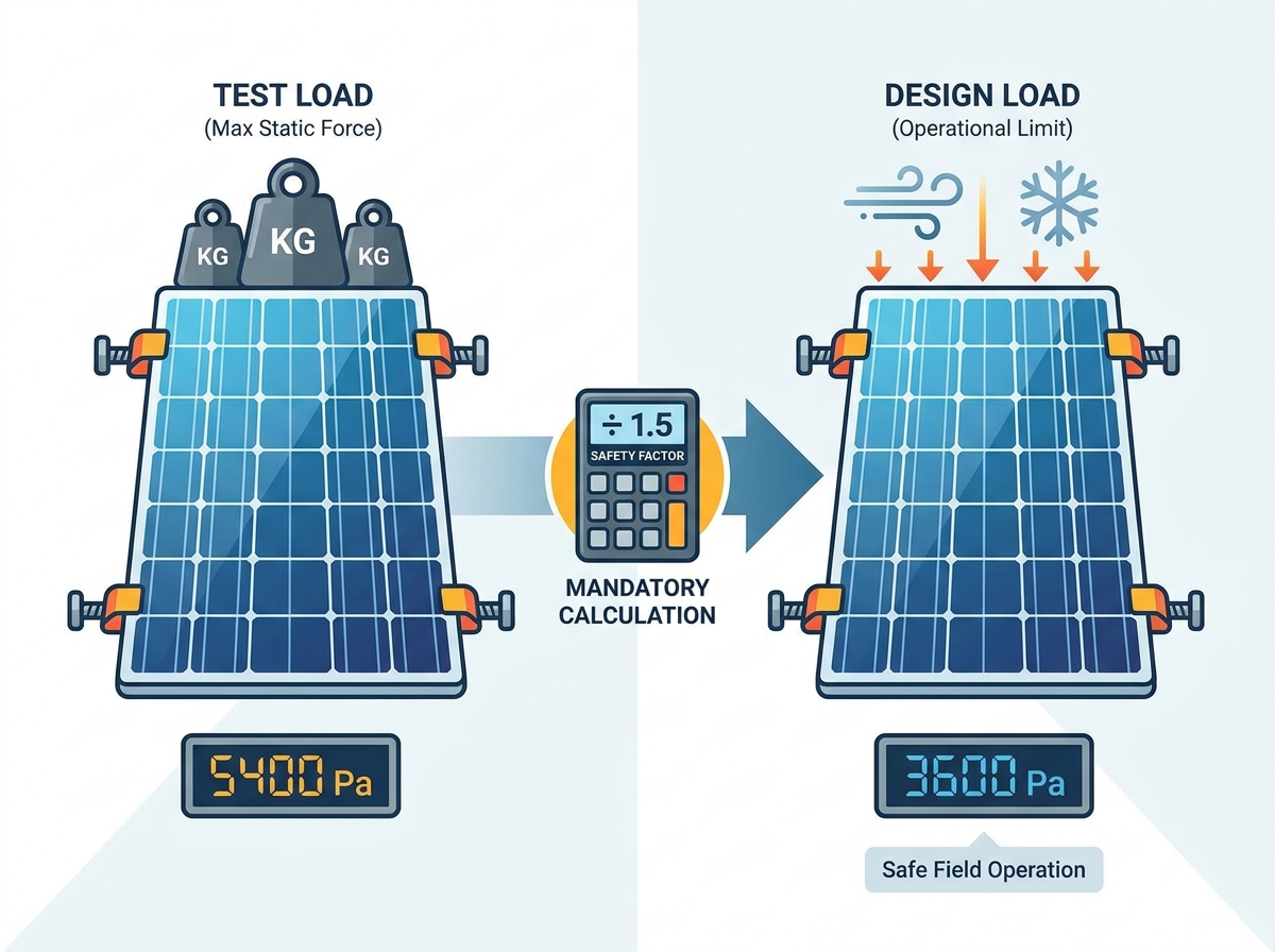
Safety Factors Matter: The "Test Load" listed on a spec sheet is not the operational limit; the actual "Design Load" incorporates a mandatory 1.5 safety factor (e.g., a 5400 Pa test load equals a 3600 Pa design load).
Mounting Dictates Strength: A commercial solar panel only achieves its rated mechanical load if secured strictly within the manufacturer’s specified clamp zones.
Certifications are Baselines: IEC 61215 and UL 2703 provide baseline static load compliance, but dynamic real-world forces often require evaluation beyond standard certification.
System Synergy: Commercial rooftop PV module selection cannot be siloed from racking selection; the two must be evaluated together to ensure compatible clamping ranges and torque specifications.
1. The Structural Reality of Commercial Solar Panel Deployments
Assessing the financial and operational risks of mechanical failure is vital for commercial installations. A failed array does not just stop producing power. It creates massive liability issues, requires expensive replacement labor, and severely damages project ROI. Engineering teams must evaluate structural rigidity just as rigorously as electrical efficiency.
Snow loads create extreme downward pressure on solar arrays. Accumulated snow adds massive weight to the module surface. This weight causes the aluminum frame to deform and the glass to deflect inward. Extreme deflection stresses the brittle silicon cells inside the module. It leads directly to cell-level microcracking. These microcracks interrupt electron flow, creating dangerous hotspots and permanently reducing energy yield.
Wind loads introduce dangerous uplift pressure. Wind drafts do not simply push against the panels. Aerodynamic forces create dynamic updrafts that pull panels away from their mounting hardware. This uplift threatens module frames heavily. It is particularly dangerous on flat commercial rooftops and high-tilt ground mounts where wind easily catches the underside of the array.
The scale variable complicates these forces further. Modern modules now routinely exceed two square meters in size. This massive surface area acts like a giant sail. As the exposed area increases, environmental loads multiply exponentially. Structural rigidity becomes the primary evaluation criterion. A highly efficient panel is entirely useless if its frame twists and shatters during a winter storm.
2. Test Load vs. Design Load: Decoding the 1.5 Safety Factor
Engineers and procurement teams must understand the critical difference between test loads and design loads. The test load defines the maximum static pressure applied to a module in a controlled laboratory setting. Laboratories typically execute these tests under standard IEC 61215 MQT 16 testing protocols. Technicians place heavy sandbags or use suction cups to stress the module until it reaches its breaking point. This number looks impressive on a spec sheet.
The design load represents something entirely different. It defines the maximum expected operational load a module can safely endure in the field. This is the actual threshold structural engineers use for site calculations. You cannot use the test load to design your system. You must calculate the design load.
The solar industry applies a strict IEC safety factor to bridge the gap between lab tests and field reality. This standard requires a 1.5 safety margin across the board. You simply divide the laboratory test load by 1.5 to find the practical design load.
Downward Pressure Example: A 5400 Pa Test Load ÷ 1.5 = 3600 Pa Design Load.
Uplift Pressure Example: A 2400 Pa Test Load ÷ 1.5 = 1600 Pa Design Load.
Misinterpreting this safety margin is a massive procurement pitfall. Buyers often look at a spec sheet and assume a 5400 Pa rating means the panel survives a 5400 Pa snowstorm. Proper commercial rooftop PV module selection requires filtering options by design load, not test load. Confusing the two leads to under-engineered arrays. It almost guarantees catastrophic failure during extreme weather events.
3. How Clamp Zones Dictate True Mechanical Strength
You can buy the strongest module on the market, but it will fail if you mount it incorrectly. The anatomy of a clamp zone is highly specific. Manufacturers define distinct regions on a module’s frame authorized for racking attachments. They usually measure these zones in millimeters from the corner of the frame. Clamping inside these zones is mandatory.
Quarter-point clamping generally yields the highest mechanical load ratings. By placing clamps roughly one-quarter of the way down the long side of the frame, the setup evenly distributes environmental stress. This configuration allows a module to achieve its advertised 5400 Pa test load rating.
End clamping, or short-side clamping, drastically reduces structural capacity. Gripping the shortest edges of a module allows the long center sections to bow and flex wildly under pressure. This configuration often drops ratings well below a 1200 Pa design load. It leaves the entire array highly vulnerable to wind uplift.
Mechanical Load Rating Comparison by Clamping Method
Clamping Configuration
Typical Test Load (Pa)
Calculated Design Load (Pa)
Primary Vulnerability
Quarter-Point (Long Side)
5400 Down / 2400 Up
3600 Down / 1600 Up
None (Optimal Configuration)
End / Short-Side
2400 Down / 1200 Up
1600 Down / 800 Up
Extreme Wind Uplift
Off-Center (Outside Zones)
Not Certified
Zero (Voided Warranty)
Frame Snapping / Glass Breakage
Specialized commercial racking systems introduce unique nuances. Trackers and rail-less mounting solutions significantly impact approved clamping zones. These systems grip the panel differently than traditional rails. They always require specific manufacturer addendums. You must verify that your chosen commercial solar panel is certified for your specific racking style.
The implementation risk here is massive. Installing clamps outside the specified tolerance window instantly voids the manufacturer's performance warranties. It also invalidates structural warranties. Installers must use torque wrenches to hit exact tension specifications. Guessing clamp placements based on convenience is a costly engineering mistake.
4. Evaluating Compliance Standards: IEC 61215, UL 2703, and Beyond
Procurement professionals lean heavily on standard certifications to gauge reliability. However, you must understand exactly what these standards measure. They provide baseline compliance, not absolute guarantees for every extreme environment.
IEC 61215 (specifically MQT 16) serves as the global standard for static mechanical load testing. It dictates exactly how labs should apply weight and measure deflection. It ensures a baseline level of structural integrity. Meanwhile, UL 2703 serves as the primary North American standard. It focuses heavily on the mounting system itself. It evaluates electrical continuity, grounding, and how racking hardware intersects with module structural limits.
We must acknowledge the difference between static and dynamic loads. Static tests fail to capture real-world conditions perfectly. Placing stationary sandbags in a quiet laboratory does not simulate a violent thunderstorm. Wind induces resonance, rapid fluttering, galloping, and cyclic fatigue. A panel flexing up and down thousands of times during a storm experiences dynamic mechanical load (DML).
Because static tests have limits, risk-averse EPCs demand extended reliability testing. They look for third-party validation beyond standard certifications. Organizations like PVEL provide scorecards based on rigorous dynamic testing. They subject panels to thousands of cycles of alternating pressure. This advanced DML testing verifies long-term frame durability. It ensures cell integrity remains intact despite repetitive environmental stress.
Choosing the right module requires a disciplined, engineering-focused decision framework. You must align your selections with local ASCE structural codes. Structural professionals create site-specific wind speed maps and snow load requirements. Your chosen panel's design loads must mathematically exceed the maximum forces predicted by these local codes.
Frame thickness and material profiles matter immensely. You might see 30mm frames on residential panels, but they often fail in commercial settings. A 35mm or 40mm anodized aluminum frame is usually necessary for high-load commercial environments. The extra thickness provides essential rigidity against dynamic updrafts and heavy snow accumulation.
Cross-referencing installation manuals is a mandatory step. You cannot buy panels and racking hardware independently. Before issuing any purchase order, you must compare the module's installation manual load tables against the racking manufacturer's approval letters. Ensure the clamp zones align perfectly with the rail spacing.
Follow this shortlisting logic to secure a reliable system:
Audit local environmental load requirements in Pascals (Pa) based on engineering reports.
Filter your module options strictly by Design Load capacity, ignoring the inflated Test Load numbers.
Verify racking compatibility, ensuring the specific roof layout allows mounting within the manufacturer's approved clamp zones.
Conclusion
Mechanical load ratings act as rigid engineering constraints, not flexible guidelines. Successfully deploying commercial modules requires strict adherence to the critical distinction between test loads and design loads. You must respect the 1.5 safety factor calculation in all planning stages. Furthermore, precise execution of clamp zone requirements is non-negotiable for system survival.
Always mandate that your engineering teams cross-reference documentation. They must compare the exact revision of the module manufacturer's installation manual with the racking provider's structural constraints. Do this before issuing any purchase order. Proper planning prevents microcracking, stops catastrophic array loss, and ensures your commercial solar assets deliver decades of reliable power.
FAQ
Q: What is the difference between a Test Load and a Design Load in solar panels?
A: The test load is the absolute maximum static pressure a panel withstands in a controlled laboratory setting. The design load is the practical engineered limit used for real-world installation calculations. You determine the design load by dividing the test load by a mandatory 1.5 safety factor.
Q: How do Pascals (Pa) convert to wind speed (mph) for solar panels?
A: Converting Pascals to wind speed is not a simple linear equation. It depends heavily on aerodynamics, the array's tilt angle, roof zones, and overall building height. Calculating exact wind speed resistance requires a licensed structural engineer to evaluate site-specific variables.
Q: Can I clamp a commercial solar panel on its short side?
A: Short-side clamping is only permissible if explicitly listed and approved in the manufacturer's installation manual. However, it usually results in significantly lower mechanical load ratings, making the panel highly vulnerable to wind uplift and structural failure.
Q: Does improper clamping void the solar panel warranty?
A: Yes, absolutely. Mounting a panel outside of the designated clamp zones, or failing to use the manufacturer's correct torque specifications, instantly invalidates both mechanical and performance warranties.
Q: How do microcracks relate to mechanical load ratings?
A: When environmental forces exceed a panel's design loads, the module glass and aluminum frame flex significantly. This bending stresses the brittle silicon cells inside, causing microscopic fractures. These invisible microcracks degrade power output and create dangerous electrical hotspots over time.